
RS-232 Cables, Wiring and Pinouts
RS-232 standards(TIA-232) are defined by TIA (Telecommunications Industry Association). RS-232 defines both the physical and electrical characteristics of the interface. RS-232 is practically identical to ITU V.24 (signal description and names) and V.28 (electrical). RS232 is an Active LOW voltage driven interface and operates at +12V to -12V where:
- Signal = 0 (LOW) > +3.0V (SPACE)
- Signal = 1 (HIGH) < -3.0V (MARK)
DTE (PC) and DCE (Modem)
In serial communications the terminal end (PC) is called the Data Terminal Equipment (DTE) and the modem end is called the Data Communications Equipment (DCE) as shown in the diagram below.
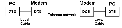
RS-232 signals have a direction (in or out) depending on whether they are with respect to a DTE or a DCE. In all the pinout diagrams below the signal direction is with respect to the DTE (PC) end.
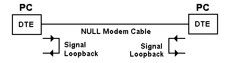
NULL Modem Connections
When PCs are connected back-to-back each end is acting as a DTE (there is no DCE in this case) and consequently certain signals may have to be looped in the connection to satisfy any input signal requirement. This is called a NULL (no) modem configuration. For example, when the DTE raises Request to Send (RTS) it typically expects Clear to Send (CTS) from the DCE. Since there is no DCE to raise CTS, the outgoing RTS signal is looped in the NULL modem cable to the incoming CTS to satisfy the DTE’s need for this signal. This is shown in the diagram below.
DB9 and DB25 Male and Female Pin Numbering
These diagrams show the male (grey background) and female (black background) pin numbering for DB9 and DB25 sub-miniature connectors. Generally Pin 1 is marked on the front of the connector right next to the pin – though you may need a magnifying glass to read it. Some manufacturers mark each pin number on the plastic housing at the rear of the connector. The male connector has the pins sticking out!
DB25 Male and Female
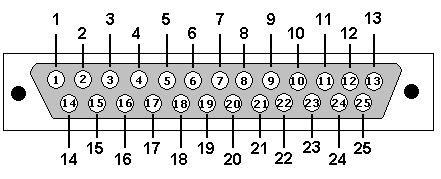
DB25: View looking into male connector
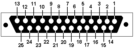
DB25: View looking into female connector
DB9 Male and Female

DB9: View looking into male connector

DB9: View looking into female connector
RS232 on DB25 (RS-232C)
| Pin No. | Name | Dir | Notes/Description |
|---|---|---|---|
| 1 | – | – | Protective/shielded ground |
| 2 | TD | OUT | Transmit Data (a.k.a TxD, Tx) (ASYNC) |
| 3 | RD | IN | Receive Data (a.k.a RxD, Rx) (ASYNC) |
| 4 | RTS | OUT | Request To Send (ASYNC) |
| 5 | CTS | IN | Clear To Send (ASYNC) |
| 6 | DSR | IN | Data Set Ready (ASYNC) |
| 7 | SGND | – | Signal Ground |
| 8 | CD | IN | Carrier Detect (a.k.a DCD). |
| 9 | – | – | Reserved for data set testing. |
| 10 | – | – | Reserved for data set testing. |
| 11 | – | – | Unassigned |
| 12 | SDCD | IN | Secondary Carrier Detect. Only needed if second channel being used. |
| 13 | SCTS | IN | Secondary Clear to send. Only needed if second channel being used. |
| 14 | STD | OUT | Secondary Transmit Data. Only needed if second channel being used. |
| 15 | DB | OUT | Transmit Clock (a.k.a TCLK, TxCLK). Synchronous use only. |
| 16 | SRD | IN | Secondary Receive Data. Only needed if second channel being used. |
| 17 | DD | IN | Receive Clock (a.k.a. RCLK). Synchronous use only. |
| 18 | LL | – | Local Loopback |
| 19 | SRTS | OUT | Secondary Request to Send. Only needed if second channel being used. |
| 20 | DTR | OUT | Data Terminal Ready. (ASYNC) |
| 21 | RL/SQ | – | Signal Quality Detector/Remote loopback |
| 22 | RI | IN | Ring Indicator. DCE (Modem) raises when incoming call detected used for auto answer applications. |
| 23 | CH/CI | OUT | Signal Rate selector. |
| 24 | DA | – | Auxiliary Clock (a.k.a. ACLK). Secondary Channel only. |
| 25 | – | – | Unassigned |

RS232 on DB9 (EIA/TIA 574)
| Pin No. | Name | Dir | Notes/Description |
|---|---|---|---|
| 1 | DCD | IN | Data Carrier Detect. Raised by DCE when modem synchronized. |
| 2 | RD | IN | Receive Data (a.k.a RxD, Rx). Arriving data from DCE. |
| 3 | TD | OUT | Transmit Data (a.k.a TxD, Tx). Sending data from DTE. |
| 4 | DTR | OUT | Data Terminal Ready. Raised by DTE when powered on. In auto-answer mode raised only when RI arrives from DCE. |
| 5 | SGND | – | Ground |
| 6 | DSR | IN | Data Set Ready. Raised by DCE to indicate ready. |
| 7 | RTS | OUT | Request To Send. Raised by DTE when it wishes to send. Expects CTS from DCE. |
| 8 | CTS | IN | Clear To Send. Raised by DCE in response to RTS from DTE. |
| 9 | RI | IN | Ring Indicator. Set when incoming ring detected – used for auto-answer application. DTE raised DTR to answer. |